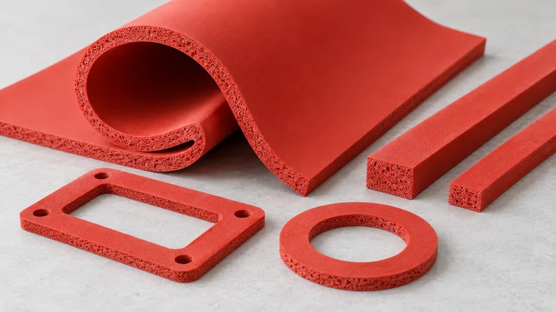
Choosing Silicone Foam sheets, strips and custom gaskets is an interface decision. The form has to match mating surfaces, local clearances and the installation sequence. A finished-looking outline does not establish that the proposed construction is supplied or that it addresses the temperature and medium conditions. Keep these questions together through the route review.
The Silicone Foam material route concerns high-temperature piping and electronic-equipment insulation/sealing under the supplied Silicone Foam material information. The customer scope directs grade selection by temperature and medium. This format guide does not add a stock-size programme, adhesive promise or machining tolerance that the material information has not confirmed.
Describe the interface before naming the format
Show the mating surfaces in a drawing and include a section where necessary. Mark the places that require contact, the thickness envelope and the features that must remain clear. A strip or gasket label does not explain a step, hole or local change in clearance. The route should follow the geometry rather than replace it.
State whether the request supplies raw material, a cut part or a complete proposed construction. Identify work that remains for the assembly team. A raw-sheet quotation and a cut-gasket quotation do not have the same scope. Procurement needs those differences visible before it compares price or asks for a sample.
Explain installation and inspection access. A part placed before a cover can have different locating needs from one installed during service. Record the actual sequence and identify any prototype-only support. The drawing can then describe the delivered form without relying on an operator improvisation that is absent from the intended process.
- Mating surfaces and thickness envelope.
- Contact zones, openings and keep-outs.
- Raw-material versus converted-part scope.
- Installation, removal and inspection access.
- Temperature/medium conditions for the complete construction.
Review a sheet-cut concept through outline and thickness
A sheet-cut concept starts with a flat material envelope and the shape required by the interface. Show the external edge, holes and local reliefs. Ask which cutting route applies to the proposed grade. Do not assume a specific process from the appearance of a reference part or from a capability stated for another family.
Keep thickness and tolerance questions attached to the drawing. The nominal thickness alone may not explain a local step or a restricted region. The designer should state which features matter most to assembly. A supplier can then identify the proposed dimensional scope rather than apply an unexplained common tolerance to every edge.
Consider how the outline is recognized and oriented during installation. A similar shape can still have a correct face or position. If identification or a carrier is needed, list it as a scope question. The review should clarify the assembly without claiming that every marking or handling feature is standard supply.
Show the part alongside the mating surfaces in the sample request. A flat outline checked on a bench may answer a drawing question but leave the installed interface open. State which decision the sample is intended to support. This keeps a useful shape review from becoming a temperature or sealing approval.
| Form concept | Geometry question | Confirm before release |
|---|---|---|
| Sheet-cut part | Can the interface be represented by a flat outline? | Grade, thickness, cutting, edges and dimensions |
| Strip | Where do the route, ends and corners fall? | Width, joints, orientation and installation |
| Custom gasket | Which holes, cut-outs and locating features are controlled? | Drawing revision, process and tolerances |
| Backed/joined construction | Which additional materials enter the interface? | Availability and temperature/medium evidence scope |
Review a strip through its path, ends and corners
A strip concept needs more than a width and length. Show the path it follows, its start and end locations and how corners are formed. Record whether the project proposes separate corner pieces or another joining arrangement. These details should come from the drawing or an explicit design discussion, not from a generic gasket template.
Explain how the installer places the strip without changing the intended geometry. Record locating surfaces and the sequence before another component constrains the part. If the prototype stretches, folds or uses temporary support, identify that observation. It can guide a revision without becoming an accepted production method by accident.
Ask who creates and inspects the joins. A supplied strip, cut lengths and a joined outline have different work scopes. The quote should identify which one is proposed. The assembly owner needs to know whether an interface feature arrives finished or must be made during installation.
Keep the joint construction connected to temperature and medium questions. A join can add a material or change the local interface. The current material record does not establish a universal joining system for every Silicone Foam grade. Ask for its scope and applicable evidence before treating the whole route as exposure-approved.
Review a custom gasket through controlled features
A custom outline can define holes, corners and cut-outs on a controlled drawing. Identify the features that locate the part and those that provide clearance. Provide a reference or datum where the design needs one. Avoid introducing an invented tolerance just to make the drawing look complete.
Ask the converter which process and inspection route applies. The material family does not prove die cutting, routing, lamination or another method for the specific grade and geometry. A proposed route can be evaluated after its assumptions are named. Keep unconfirmed capability visible instead of describing it as a standard service.
State how the part is supplied and installed. A one-piece outline may simplify locating in one assembly while another geometry requires a different approach. The sample should show the actual mating parts and access constraints. Do not rank the forms without the interface that gives the comparison meaning.
The Silicone temperature/medium selection guide explains the exposure brief behind the form. If a custom outline changes thickness, contact or joining, return those changes to the grade and assembly review. The shape cannot inherit an unqualified temperature result from the material name.
Treat backing and added layers as part of the construction
If backing, a carrier or lamination is proposed, identify every added material and its location. Ask whether the construction is supplied and what evidence applies under the project's temperature and medium conditions. Do not infer self-adhesive availability from an image or from the word gasket.
Separate a handling aid from a functional interface requirement. The assembly owner should state why the added material is proposed and what it must do. A temporary prototype aid should remain identified as temporary. This prevents a simple installation observation from approving a construction that the evidence does not address.
When comparing a backed and unbacked part, record both the form and the material differences. Another thickness, edge or carrier can affect placement. The reviewer should describe the configuration rather than assign the observation to Silicone Foam alone. The whole proposal needs an explicit boundary.
- Identify added materials and joins.
- State their purpose and supply owner.
- Request applicable temperature/medium evidence.
- Review installation in the intended configuration.
- Preserve any unresolved construction requirement.
Confirm measurement and supply scope
Ask for the proposed grade, method and dimensions with the quotation. The Silicone density and hardness guide clarifies the provisional material records. Density and Shore C are not format availability or exposure approval. They should remain attached to the grade and method rather than substitute for a converted-part drawing.
For method terminology, consult the ASTM International catalogue and the NIST measurement resources. These public references support an engineering conversation. They do not prove a Green Foams test result, certificate or conversion tolerance.
Expected volume can help define the request, while tooling and commercial conditions remain separate questions. The material information does not supply a universal MOQ, capacity or lead time. Ask for those conditions against the proposed form without inventing standard values or promising a particular route before confirmation.
Release an identified converted part
The industrial/electronics interface brief preserves drawing, construction and sample ownership. Record the exact format and the observations accepted. A shape can be approved while exposure evidence remains open, provided the approval scope says so. Do not turn partial acceptance into a universal sealing or thermal claim.
Review changes to the grade, thickness, edge, join, backing or mating parts. Each can alter the proposed construction or installation. Retain the previous sample and identify which observations need repeating. The form decision should remain tied to the same controlled interface throughout the project.
A good sheet, strip or custom-gasket comparison therefore explains the drawing, work scope and evidence boundary. It identifies what arrives finished and what remains to be evaluated. The useful result is a reviewable Silicone Foam form for a defined piping or equipment interface, with supply and exposure questions preserved.
Ask how the converted parts will be identified when similar outlines arrive together. An orientation mark or drawing reference can make the reviewed installation easier to reproduce, but its availability and method remain scope questions. The assembly owner should explain the identification need without treating a convenient production filename as a controlled part reference.
Keep receiving observations linked to the drawing. If an edge, join or backing differs from the reviewed sample, identify its location and construction before changing the assembly method. Route the proposed correction to the appropriate owner. A practical handling adjustment can be useful feedback, but it should not silently create a new approved Silicone Foam construction.