Distinguish format from confirmed capability
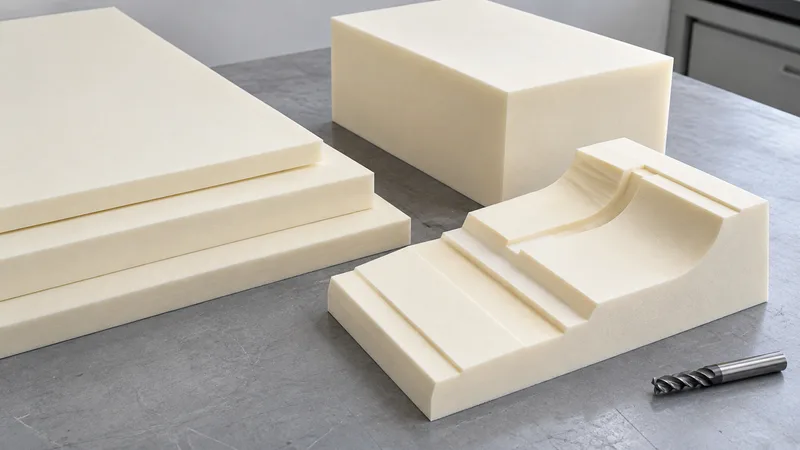
Rigid PU Foam sheets, blocks and CNC-cut cores are format routes for insulation layers, models and structural cores. The client knowledge base mentions mold-in-foam and CNC processing directions, but it does not confirm stock dimensions, equipment ownership, universal machining tolerances or a minimum feature size. Keep those fields [需确认] for the proposed grade.
A sheet concept is useful when the component has predominantly planar sections. Ask which thickness, face condition and cut outline the project needs. A block concept can frame shaped or model work where stock preparation and orientation matter. Neither term proves that a particular size is kept in stock or can be delivered under an assumed lead time.
- Record the controlled component and counterpart revisions.
- Identify thickness, orientation and critical interfaces.
- Keep unverified material and process fields [需确认].
- Assign the next evidence question to its owner.
CNC-cut work expresses a drawing-controlled profile. The request should identify datums, machining faces, pockets, tool access and relevant tolerances. A molded concept introduces other tooling and forming questions. Do not treat molding and CNC as interchangeable processes merely because both can be discussed around the same outside shape.
Start at the Rigid PU Foam product hub with a controlled model and drawing. State which features are fixed and which may be revised. A format proposal becomes useful when it preserves the component purpose rather than presenting a generic claim that any shape is available.
Define stock, orientation and machining references
Show the final envelope and local thickness separately from the proposed starting stock. A block may be oriented to support a particular machining setup, and a sheet may require a reference face. Request confirmation of stock allowance and preparation instead of assuming the final dimensions define the starting material.
Mark the datum surfaces used by assembly and inspection. If one face meets a panel skin or a model fixture, identify it on the drawing. A machining reference that differs from the assembly datum can create a comparison problem unless the relationship is explicitly defined.
Record orientation in both the part drawing and any material evidence. Compressive-strength specimens and finished geometry need their own identified directions. Do not assume that a material result measured in an unspecified direction applies to a differently oriented core solely because the grade label is the same.
Keep critical tolerances distinct from informational dimensions. The knowledge base does not establish universal Rigid PU conversion capability. Ask the process owner to confirm which dimensions can be controlled, how they will be measured and what drawing revision represents the proposed manufacturing route.
| Decision field | Input or record | Review purpose |
|---|---|---|
| Sheet | Planar layer and section | Confirm face, thickness and outline |
| Block | Starting stock for shaped work | Confirm stock and orientation |
| CNC core | Datums, pockets and access | Confirm geometry and tolerance |
| Molded concept | Tooling and finishing proposal | Confirm actual route scope |
| Assembly | Facings, joints and hidden features | Plan inspection before joining |
Make features and edge treatments reviewable
Add sections through pockets, steps, tapered edges and local recesses. Identify the remaining thickness beneath each feature and the adjacent component it serves. A pocket that clears hardware and a recess that sets a facing position can have different priorities even when they look similar in a rendered model.
Identify feature access and the surfaces that must remain intact. A proposed toolpath or setup can require a change to geometry, but the reviewer must explain that change before the drawing is released. Do not promise a feature limit, cutter radius or surface finish that the client record has not confirmed.
Show how neighboring core pieces meet. A multi-piece insulation layer or assembled model needs part identification, edge alignment and a defined counterpart relationship. Record the thickness at each interface, the assembly reference surfaces and the inspection method. The project owner should define acceptance for the actual core construction.
If a facing or bond surface is involved, identify it separately from a trim surface. Ask what condition is required before joining and how it will be inspected. Actual adhesion, surface preparation and interface strength need evidence for the proposed construction; the format name alone cannot prove compatibility.
For a pocket that approaches a facing surface, show its depth from the nominated datum and the remaining local section on a separate detail. Ask the process reviewer to identify how that depth will be produced and inspected, including any access limitation. If another setup or a revised corner is proposed, place the change on the drawing for design review. The route proposal should resolve a specific feature rather than silently replace the geometry that the facing interface requires.
Compare CNC and molded proposals on the same drawing
A fair route comparison keeps function, critical sections and counterpart interfaces visible. Ask each proposed process to identify stock assumptions, forming or machining steps, finishing scope and inspection method. Record where the process requires a geometry adjustment rather than treating two similar looking samples as equivalent constructions.
For CNC work, identify machining references, access restrictions and the sequence needed to reach important features. For a molded concept, ask about tooling inputs, form features, revision handling and finishing. These are discussion questions, not statements that Green Foams operates every required process in-house.
The source ranges 30–200 kg/m³ and compressive strength 0.2–5 MPa remain [需确认]. A process preference does not validate a grade. Use the density and strength guide to request the material record associated with each route.
Consult ASTM International and the ISO standards catalogue with the test owner for measurement terminology. Public method references do not establish a supplier machining tolerance or certify the resulting component.
Inspect before joining and after assembly
Plan dimensional inspection around the drawing datums and feature priorities. Check critical thicknesses, outline, pockets, edges and facing references before the core is concealed. Record the method and sample identity. This protects an important local section from being lost behind an otherwise acceptable external panel appearance.
Review how the core reaches the workstation or assembly fixture. Identify orientation, handling points and part separation for a multi-piece set. Damage or a version mix-up can obstruct a geometry review, so record the intended packing and identification inputs with the sample route.
Assemble the relevant counterparts and observe fit, alignment and access. A sample may reveal the need to change a pocket, edge or placement sequence. Assign that change to its drawing revision. The observation shows the reviewed geometry and does not establish thermal conductivity, compressive performance or lifetime.
If the sample purpose involves a bond interface, separate the fit check from the interface evidence. A core that sits against a skin is not automatically an approved bonded construction. Ask the engineering owner what method and acceptance criterion are required before the interface is released.
Control format changes through procurement
Use the thermal and structural core selection guide when a format proposal affects the function. A change from a planar layer to a shaped core, or from a single piece to a set, can require another geometry and evidence review.
The cold-chain and construction brief preserves the route in quotation. State the final drawing, stock or process assumptions, material questions, counterpart references and inspection scope. Ask proposals to identify their differences from that baseline.
Keep commercial scope explicit. Expected volume and revision timing help frame the proposal, while actual stock, minimum order, tooling costs, production capacity and lead time require confirmation. A resource guide must not invent those terms or turn a requested format into a blanket manufacturing promise.
After approval, retain the sample, grade proposal and drawing references. Repeat affected checks when orientation, thickness, stock source, processing or facings change. A controlled format decision describes a practical route to one component, with known geometry and visible open questions.
Prepare a meaningful first-article record
Before the first component is reviewed, identify the drawing features that will demonstrate the proposed route. Select representative pockets, local sections, datum relationships and edge treatments. Ask the process and quality owners how those features will be measured. A first-article review should make the critical construction understandable instead of collecting only a photograph of the outside shape.
Compare the sample to the proposed route and list deviations. A changed starting stock, another machining setup or an altered facing reference should be explained. The reviewer can then decide whether the deviation is acceptable, requires a drawing change or represents another sample request. Avoid treating a workshop adjustment as an automatically approved production process.
For a multi-piece set, check each component identity and the relationships among pieces. Record which surface or edge defines assembly alignment. The set may fit while one hidden feature remains unresolved, so retain individual inspection fields instead of reporting only a broad assembly pass.
Keep the first-article record separate from quantitative material evidence. A dimensional check cannot establish compression stress or a thermal result. Conversely, a grade report cannot establish the tolerance of a machined pocket. Both records can support the project when their scopes and ownership remain distinct.
- Define the component function and load or thermal question.
- Request the proposed grade and relevant methods.
- Review geometry, interfaces and processing scope.
- Preserve the sample identity, evidence and approval boundaries.