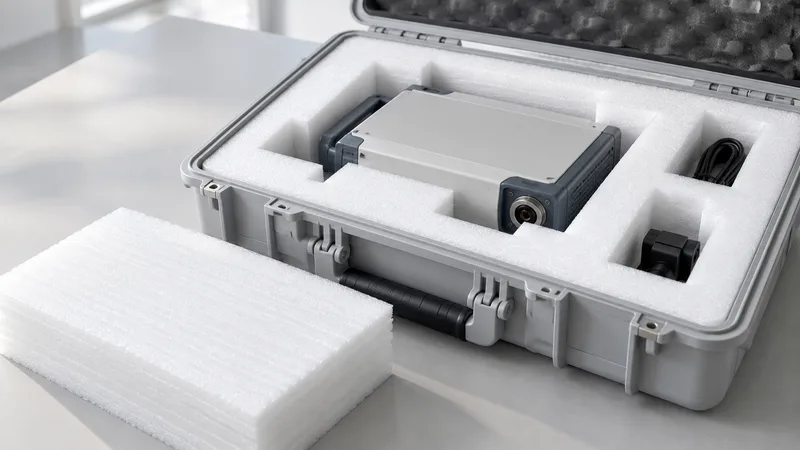
EPE foam inserts for electronics and instruments are packaging components that organize a product inside an enclosure while creating separation from surrounding surfaces. The insert may use cavities, profiles, layers or cut features, but its usefulness comes from how it works in the complete package. A cavity that looks accurate in isolation can interfere with a connector, trap a cable or prevent a carton from closing. This guide explains how to prepare the brief and review the proposed construction without inventing unconfirmed performance claims.
The EPE Foam product page presents sheets, rolls, tubes or profiles and custom die-cut routes as discussion formats. The project source describes EPE for electronics and precision-instrument transport packaging, while density and sheet-thickness values remain parameters marked [需确认]. Treat the page as a starting point for material and format selection. The proposed grade, dimensions, conversion details and evidence still need project confirmation.
Build the insert brief around the actual product
Begin with a dimensioned drawing or representative sample. Show the overall envelope, projections, mounting features and surfaces that may carry contact. Mark the display, controls, switches, connectors, vents, cable exits and finished faces that need clearance. If a feature is difficult to explain in two dimensions, include photographs as context while keeping the drawing or sample as the dimensional reference.
Separate support surfaces from keep-out surfaces. Support surfaces are areas where the proposed insert may locate the product. Keep-out surfaces must remain free of contact or pressure because of a connector, control, finish or functional feature. This distinction helps the designer place material where it can stabilize the product without transferring handling loads to a sensitive component.
List every accessory that travels with the product. Cables, adaptors, probes, manuals or removable modules can change the insert layout. Give each item its own envelope and removal path. Decide whether it needs an individual cavity, a divider, a separate layer or another package component. An insert approved with the main instrument alone is not approval for the complete kit.
- Identify product orientation, support surfaces and features that require clearance.
- List accessories, cable paths, separate cavities and the order in which parts are loaded.
- Provide enclosure dimensions, lid or flap details, partitions and available stack-up.
- Record open questions about electrical, cleanliness, chemical or regulatory requirements.
Describe the packing and unpacking sequence in plain language. Note where the operator grips the instrument, whether a cover is installed before closing and how the recipient lifts the product out. If the package is reused, explain how the insert is reloaded and stored. A design that locates the instrument but blocks a connector during removal creates a handling problem that a static drawing may miss.
Define the protection objective with an acceptance method. The requirement may be stable orientation, prevention of product-to-product contact, protection of a display or a buffer during handling. If transport performance must be assessed, name the agreed method and conditions. Do not substitute an unsupported claim about drops or shock for a documented evaluation plan.
Choose a cavity, layer or profile that matches the package
A custom cavity can control orientation and separate an instrument from accessories. Identify the cavity entry direction, support points, depth and clearance around controls. Avoid placing a tight wall beside a connector simply because that edge is convenient to draw. The sample should show how the product enters, seats and exits using the planned operator grip.
Layered inserts can provide a base, compartment layer and cover while keeping accessories organized. Define the purpose of each layer and the order of assembly. A cover that protects a top surface may also reduce the clearance available to a switch or knob. Check the stack-up inside the enclosure and review interfaces between layers. Do not assume that a common thickness or layer count works for every instrument.
Profiles, rails or channels can support long bodies, handles or cables. Identify which feature the profile contacts and how it is retained during movement. If a tube or shaped profile is part of the package, describe its cut length, opening and relationship to the enclosure. A format photograph demonstrates an example of form; it does not establish a fit for a different instrument.
Sheets and rolls can supplement an insert. A sheet may separate a lid from a display, while a roll may wrap an exterior surface before the instrument enters the cavity. Review those pieces as part of the assembly because they change the available clearance and removal sequence. The insert brief should show every component needed for the packed configuration.
| Insert review | What to define | What to check in the sample |
|---|---|---|
| Product cavity | Envelope, support surfaces, keep-out zones and loading direction | Orientation, contact, clearance and removal |
| Accessory cavity | Accessory list, cable path, separation and retrieval method | Placement, access and interference with the main product |
| Enclosure interface | Internal dimensions, closure features and stack-up | Carton closure, movement and edge interference |
| Release evidence | Grade, construction, revision and acceptance criteria | Recorded result for the same drawing and configuration |
Conversion details need the same care. Custom cutting may be discussed as die-cut, CNC or another route, but a process name does not establish a tolerance or edge condition. Ask which dimensions are critical, which will be inspected and how revisions are controlled. Tie the material grade and construction to the drawing under review. If an adhesive, laminate or other conversion is proposed, list it explicitly rather than inferring it from an image.
Protect sensitive features through fit and handling review
Use the sample to confirm that support contacts occur where intended. Check whether a display or finished face touches the insert, whether a control can be actuated accidentally and whether a connector has clearance on every side. Load the product with the actual accessories, close the enclosure and observe the stack-up. Then remove it using the planned grip. Record interference and movement instead of relying on a visual impression.
Review cable and accessory access separately. A cable can bend around a cavity edge or become trapped beneath a cover. An adaptor may need to be removed before the main instrument. A manual may sit above a control and create a closure issue. Include those steps in the sample and mark any change required to the cavity, layer or divider.
Do not confuse fit with transport performance. Fit checks the product, insert and enclosure in a defined configuration. A transport evaluation examines that packed assembly using an agreed method and conditions. A successful fit sample does not prove a transport result, and a transport result does not prove that an operator can load the product consistently. Record both decisions separately.
Electronics can introduce requirements beyond mechanical protection. Record any electrostatic, cleanliness or contact-material requirement in the brief. The appearance or color of EPE does not establish a special electrical property, and a generic material description does not establish regulatory compliance. Request grade-specific evidence where the buyer requires it. Keep open requirements marked pending until the evidence is reviewed.
Confirm EPE grade, dimensions and evidence
The planning record lists EPE density of 18–45 kg/m³ and sheet thickness of 0.5–100 mm as customer-provided parameters marked [需确认]. These values are discussion inputs, not a guaranteed range for every insert. Ask which grade and construction apply to the proposed design, then connect any data sheet or test record to that grade. Confirm units, test method and conditions for properties used in acceptance.
Standards references can help define a testing brief. The ASTM International standards catalogue and ISO standards catalogue provide starting points for terminology and methods. They do not prove that a proposed EPE insert complies with a standard or that Green Foams holds a certification. Select the applicable method with the project team and ask for the records needed for the actual construction.
Different properties may be reported under different conditions. Keep test method, units, specimen details and conditioning with each value. Do not turn a broad reference range into an inspection tolerance without agreement. If a buyer needs a dimensional, electrical or cleanliness check, identify who performs it and what result constitutes acceptance.
Commercial scope should be recorded with the technical brief. Share expected volume, delivery context, packing instructions and repeat-order assumptions. The current source set does not confirm minimum order quantities, sample fees, capacity or lead times. Those terms need a quotation based on the approved construction. A technical sample helps the conversation but does not silently establish a commercial agreement.
Approve a complete sample and control revisions
Prepare a sample review checklist before the insert arrives. Include the product revision, accessory list, enclosure, material grade, cavity dimensions and open requirements. Check loading, orientation, support, clearance, closure, movement and removal. Record the configuration tested, including any sheet, roll, cover or divider used alongside the insert.
- Send the drawing or representative instrument sample with critical dimensions and keep-out areas.
- Provide accessory envelopes, enclosure details, loading direction and the planned removal sequence.
- Review the proposed EPE grade, construction and conversion through a complete loaded sample.
- Record fit results, evidence, revision, inspection points and unresolved requirements before release.
Use revision control when a product, accessory or enclosure changes. A small connector relocation can alter a cavity wall. A new cable can change the accessory layer. A lid revision can reduce stack-up. Record the drawing and sample covered by the approval, and repeat the relevant checks when the configuration changes. The approval belongs to a defined package rather than to every future version of the instrument.
Keep a short decision record for engineering and purchasing. State why the insert format fits the handling route, which evidence supports the proposed grade and which questions were closed by the sample. This record helps a later reviewer understand the decision without relying on a product photograph or memory of an earlier discussion.
When the brief is ready, use the EPE Foam drawing-to-sample workflow to request a review. For a broader packaging comparison, read EPE foam vs EVA foam for protective packaging and keep the same product, enclosure and acceptance criteria when comparing materials. A complete brief gives the supplier and buyer a shared basis for a useful insert sample.