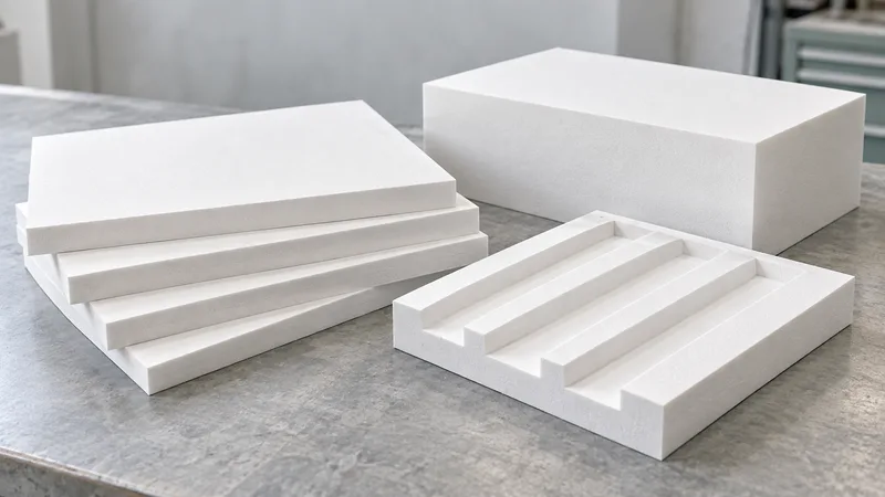
Choose the format from the core drawing
PET Foam sheets, blocks and machined core panels organize different geometry requests. The client knowledge base covers sandwich structures, floors and side panels and identifies density and structural-processing adaptation as planning directions. It does not confirm universal stock dimensions, specific machining methods or tolerance limits.
A sheet concept can suit a predominantly planar core. Ask for the proposed thickness, datum face and outline. A block concept can frame stock for a shaped component or another local section. A machined panel expresses features that must be controlled by the drawing rather than interpreted from a photograph.
- Define the datum face before specifying machining features.
- Pair each joining edge with its neighboring piece and revision.
- Identify inspection access before facing attachment conceals local sections.
These are options to review, not an available-stock catalogue. The proposed grade, size and conversion route need confirmation together. Do not create a claimed standard sheet size, a minimum order or a cutter feature limit from the material family or the broad client description.
Begin at the PET Foam product hub with the panel section and feature drawing. Identify fixed interfaces and dimensions that may be revised. This lets the process reviewer discuss alternatives while preserving the purpose of the sandwich construction.
Separate starting stock from finished geometry
Show the final envelope and local sections separately from the proposed stock. A drawing-controlled pocket, taper or relief is not the same input as a starting block size. Ask the manufacturer to identify stock preparation and allowances where relevant to its proposal instead of assuming the final dimensions define all material needs.
Identify the datum face that locates the core against its counterpart. Keep machining references connected to assembly references. If a process setup uses another surface, record the relationship so that quality can understand how the finished geometry will be inspected.
Record orientation on the part and material references. A compression report may identify a loading direction, while the panel drawing identifies how the core is installed. Those records should not lose their directional context during machining or packing. Ask for clarification if the proposed grade record omits that information.
Keep critical dimensional priorities visible. Local core thickness near an attachment can have another significance from an outer trim edge. The current source does not establish a universal conversion tolerance, so request the proposed value and inspection method for the actual feature and route.
| Decision field | Input or record | Review purpose |
|---|---|---|
| Sheet | Planar core and reference face | Confirm size and thickness |
| Block | Starting stock and orientation | Separate stock from final form |
| Machined panel | Datums and local feature sections | Confirm route and tolerance |
| Piece set | Neighboring edges and identities | Control assembly alignment |
| Inspection | Features before facing attachment | Preserve evidence scope |
Make local features and panel-piece relationships explicit
Add sections through recesses, steps, holes and tapered regions. State the remaining thickness and the counterpart component served by each feature. A cut-out can affect assembly space or load introduction, and its purpose should be known before the process owner suggests a revised geometry.
For a multi-piece core, identify each piece and show how it meets its neighbors. Record edge alignment, orientation and assembly references. A set that looks complete on a table may still contain an unclear interface or version mismatch when placed between facings.
Show facing and bond surfaces separately from noncritical trim surfaces. Ask which surface condition or geometry needs inspection before joining. Actual adhesive compatibility, preparation and interface strength require evidence for the proposed construction and cannot be supplied by a format label.
Structural panel review needs core sections, counterpart alignment, load-path inputs and controlled interfaces. Identify the relevant support surfaces and the material remaining around local features. A panel approval should follow the project evidence plan and the reviewed construction, with geometry observations and formal performance requirements preserved as separate records.
For a panel-piece boundary, identify the two matching edges and their revision references on the layout drawing. Show which face establishes alignment and where the joint sits relative to facings, supports and local cut-outs. Ask quality which relationship must be checked before the set is covered. A dimensional record for one piece cannot describe the neighboring piece or their assembled relationship, so retain the paired references when the process proposal splits an originally continuous core into separate components.
Review machining scope and material evidence together
Ask the proposal to identify the conversion route, process ownership, feature access, setup and finishing assumptions. The client describes processing adaptation, while actual PET machining capability remains pending confirmation. A digital model or a finished-part image cannot establish equipment, tolerance or repeatable production scope.
The proposed grade should accompany the route. The source retains 60–250 kg/m³ and compression stress 0.5–3 MPa as pending confirmation, without a grade-by-grade map. Use the density and compressive-strength guide to request a material record tied to the sample.
Keep processing evidence distinct from material testing. A dimensional sample can demonstrate a pocket or datum relationship, while a compression specimen demonstrates a result under its method, direction and state. Neither record automatically establishes the other requirement.
For method language, use ASTM International and the ISO standards catalogue with the responsible owner. Public directories do not certify a machined panel or validate a supplier tolerance.
Request a proposed inspection view for features that cannot be reached after joining. Identify the measurement reference and whether the check uses the finished datum face, a temporary setup or another agreed method. If a datum surface is altered during a later conversion step, the process owner should explain how the feature remains traceable to the panel drawing. This gives the first-article review a specific measurement question without inventing a universal machining tolerance or an available inspection capability.
Inspect the core before facings conceal it
Prepare the inspection record before the sample is made. Select the datums, local sections and features that matter to the panel. State the measurement method and whether a counterpart reference is needed. A hidden recess or bond surface cannot be reconstructed reliably from the external appearance of a finished panel.
Record sample identity and deviations individually. If a process adjustment changes thickness, an edge or the assembly datum, identify it on a revised drawing. A first-article acceptance should explain what was reviewed instead of reporting only that the overall piece looks acceptable.
Retain piece orientation through packing and assembly. Fit checks show alignment and access, not panel strength, fire or fatigue results. The quote must distinguish stock, conversion, facing work and tests, with availability and terms separately confirmed.
Carry format decisions into the panel brief
The wind, rail and marine panel brief preserves the proposed grade, format, local features, interfaces and approval owners. Use it to request quotation against one controlled construction rather than a generic core family.
If a format proposal changes the component function or load-path inputs, return to the PET sandwich selection guide. A new local section or multi-piece concept can require another engineering review even when the outer envelope is unchanged.
Use a piece-and-feature delivery schedule
A machined PET core set needs more than a list of outside dimensions. Matching edges must identify one another, and a feature hidden by a facing needs an inspection reference before joining. A proposal to split a continuous core is a construction alternative, not merely a packing change.
| Piece / feature | Drawing and assembly reference | Delivered work / check before facing attachment |
|---|---|---|
| [piece identity] | [datum face, orientation and installed location] | [stock / partially converted / finished; supplier response] |
| [neighboring edge pair] | [matching piece identities and edge detail] | [paired alignment observation and inspection reference] |
| [local recess or attachment region] | [section detail and remaining core thickness] | [measurement method and unresolved features] |
| [facing interface] | [surface reference and joining party] | [required pre-assembly condition; interface evidence separate] |
| [route change] | [revised feature or piece layout] | [drawing disposition and checks to repeat] |
- Receiving checks identity and orientation against the piece schedule.
- Quality retains the hidden-feature inspection with the sample before it is covered.
- The panel designer decides whether a new piece boundary or local section is acceptable.
Compare raw-stock and machined-set offers only after their remaining work is visible. Do not infer stock sizes, tolerances, machining ownership or production capacity from the format name.