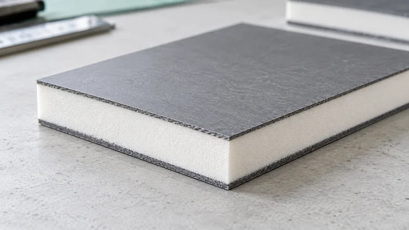
Identify the sandwich function and the actual component
How to choose PET Foam for sandwich structures begins with the panel drawing and its function. The client knowledge base places PET in sandwich structures, floors and side panels, with wind, marine, rail and building application directions. These directions do not establish a completed project, certified panel or universal structural grade.
Name the component and the role of the core within it. A floor, side panel and another sandwich part can share a core family while having different supports, facings and local attachments. The inquiry should explain what the core is expected to contribute and which assembly questions the project engineer must resolve.
- Panel section: identify both facings and the installed core orientation.
- Local detail: show the core remaining at attachments, recesses and supports.
- Evidence split: keep bare-core records distinct from interface and panel evaluation.
Show the panel stack and identify both facings. Mark the thickness and orientation of the proposed core, together with supports and important local features. A photograph of a foam sheet cannot identify the full construction or the conditions used to evaluate it.
Start with the PET Foam product hub and send the controlled section drawing. State whether the next step is material data review, machining development, panel fit or formal evidence. This keeps the selection purposeful while avoiding unsupported claims about stiffness, fatigue resistance or application approval.
Define the geometry and the load introduction
Record the overall panel dimensions and local core sections. A recess, tapered edge or cut-out can alter the material remaining near an attachment or support. Identify why each feature exists and which dimensions need review. Total panel thickness alone does not describe every local construction.
Describe how loads enter the proposed panel. Mark distributed surfaces, support locations and local attachments as engineering inputs. The material compressive-strength record addresses a defined specimen condition; it is not an allowable load for every floor, side panel or wind component made from that material.
Keep the load direction traceable to the core orientation. If a test report identifies a specimen direction, preserve it in the grade record and compare it with the drawing. If orientation is unspecified, ask for clarification rather than assuming the value applies to every loading arrangement.
Ask the project owner which assembly analysis or tests are required. Facings, geometry, interfaces and supports form one construction whose evidence must be evaluated together. The guide does not create design loads, safety factors or a panel-capacity calculation from the provisional client ranges.
| Decision field | Input or record | Review purpose |
|---|---|---|
| Component | Sandwich, floor or side panel | Identify the actual function |
| Geometry | Core sections and local attachments | Review load introduction |
| Interface | Facings and proposed joining | Keep compatibility separate |
| Grade | Density and compression stress methods | No invented correlation |
| Evidence | Specimen and assembly scope | No implied application approval |
At a local attachment, provide a section showing the core, both facings, the attachment and the supporting counterpart. Mark the region where the engineer intends the load to enter and any recess that changes the remaining section. Ask which configuration the next sample must represent. This detail gives the reviewer an actual construction to assess; it does not create a local load allowance from the material stress range or imply that a nearby fit observation validates the attachment.
Treat facing and bond interfaces as their own requirement
List the facing materials and proposed interface construction. Identify whether joining, bonding or mechanical retention is part of the request and who owns that scope. A core material name does not establish compatibility with every facing, adhesive or manufacturing condition.
Define the surfaces that will become hidden during panel assembly. Ask which dimensions, preparation or condition must be inspected beforehand. A sample that aligns with a skin demonstrates a geometry observation only; interface strength needs the applicable evaluation and acceptance requirement.
If a proposal changes the facing or joining route, record it as a construction change. Ask the engineering owner what evidence remains relevant and what must be repeated. A new bond surface can matter even when the core density and outside dimensions remain unchanged.
Use the wind, rail and marine panel brief to preserve these counterpart inputs. The brief helps purchasing retain the actual construction rather than treating all PET panels as interchangeable approved systems.
If different panel candidates use different facings, keep each stack identified in the selection record. Compare the proposed interface and geometry questions before deciding whether the same material specimen evidence is relevant. A facing substitution can leave the core designation unchanged while altering the construction under review. The design owner should state the additional evidence needed for that candidate rather than letting procurement compare the offers using density as the only differentiating field.
Request the proposed grade without inventing a correlation
The source retains density 60–250 kg/m³ and compressive strength 0.5–3 MPa as pending confirmation. It does not map density endpoints to stress endpoints grade by grade. Request the proposed grade and technical record rather than creating a density-to-strength chart from the two ranges.
Density is a mass-to-volume property for an identified specimen. Compressive strength is a stress result from a defined compression procedure and criterion. Preserve MPa, specimen state, dimensions, conditioning and loading direction. Do not call the strength an indentation hardness scale or infer a panel rating from it.
The PET density and compressive-strength guide explains the evidence fields. Ask what the report actually measured, then have the responsible engineer decide how it supports the proposed sandwich construction.
For method terminology, use ASTM International and the ISO standards catalogue. These public directories cannot certify Green Foams material or replace the grade-specific report that the project needs.
Review format and processing against the panel
A planar sheet, a block for shaped work and a machined panel are different starting concepts. Select them from the core drawing, local features and inspection priorities. Actual size availability, density customization and structural-core processing capability remain pending confirmation for the proposed route.
The sheets, blocks and machined panel guide identifies datums, orientation and feature questions. A preferred conversion route should preserve important core sections and facing interfaces, or clearly state the geometry change being proposed.
Record what the sample will demonstrate. A machined piece may support feature review; a specimen may support a defined material test; a panel sample may support assembly evaluation. Keep their identities and purposes separate so a machining observation is not reported as structural or fire evidence.
Inspect critical dimensions before the core is covered. Then review the relevant facings and supports under the agreed assembly conditions. A successful fit can move the geometry decision forward while stiffness, fatigue, environmental and compliance requirements remain explicit evidence questions.
Use application directions without implying approval
The stated sectors are application directions, not approvals. Assign relevant environmental or sector requirements to the actual panel construction; a new assembly does not inherit another panel’s evidence.
Shortlist a construction, not only a density
For the PET floor and side-panel directions in the material record, the useful comparison is between identified panel constructions. A recess beside an attachment can leave less core locally than the nominal section suggests. The next sample should expose that detail and its facing/support relationship rather than merely repeat the full-panel outline.
| Candidate construction | Question that can exclude or hold it | Decision / missing input |
|---|---|---|
| [core, facings and support layout] | Does the section preserve the required attachment and remaining core geometry? | [compatible geometry / revise / unresolved; detail reference] |
| [same core with another facing or join] | Is the interface evidence applicable to this stack? | [record reference or interface evaluation needed] |
| [different grade or orientation] | Does the compression report describe the relevant criterion and direction? | [applicable material input / clarification needed] |
| [sector requirement] | Is there evidence for this panel rather than only bare core? | [required record and responsible project party] |
Instructional example: a panel-piece candidate can fit the outline but leave the attachment region undocumented. Keep the outline observation and hold the attachment decision. Changing to a denser proposal does not answer the missing geometry or interface question.
- Compare PET proposals on the same drawing and requested evidence scope.
- Identify changes in facings and local sections before attributing a difference to the core grade.
- Request a specific material or assembly record for each open requirement; do not turn a sector label into acceptance.